How to Read HVAC Wiring Diagrams
Demystify your furnace or AC with our guide to HVAC wiring diagrams. Learn to identify symbols, colors, and components like a professional technician.

Mastering the Map of Your HVAC System
Opening the service panel of your furnace or air conditioner often reveals a complex web of colorful wires and a cryptic sticker known as the wiring diagram. For many homeowners, this looks like a bowl of alphabet soup.
However, understanding how to read HVAC wiring diagrams is a vital skill for troubleshooting and safety. This guide will break down the symbols and logic used by manufacturers so you can navigate your system with confidence.
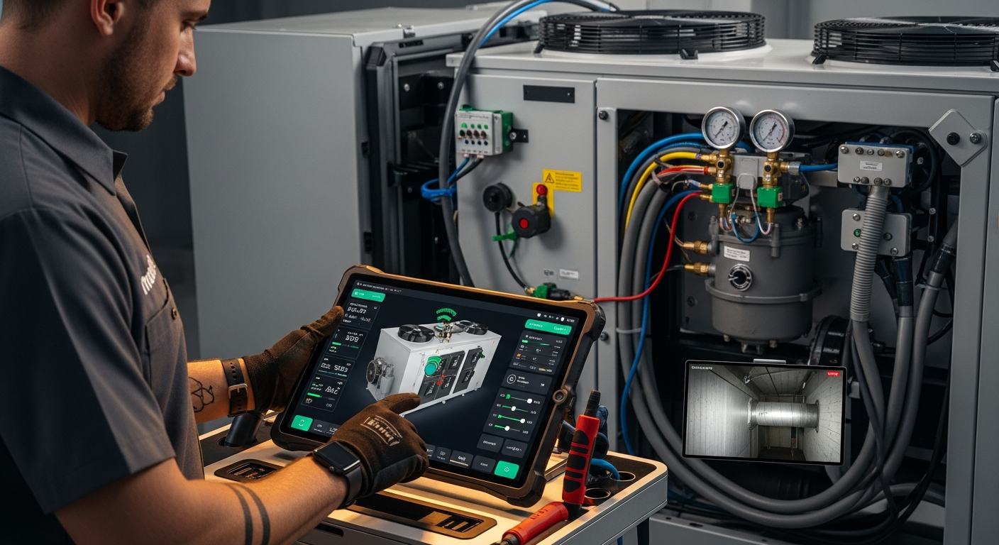
If a project feels over your head, remember you can always find certified professionals at HVACDatabase.com to ensure your electrical work is up to code.
Why the Wiring Diagram Matters
An HVAC wiring diagram is a schematic representation of the electrical circuits within your unit. It shows how power flows from the source to components like the compressor, blower motor, and thermostat.
By learning to read these charts, you can identify blown fuses, loose connections, or failing components. Before you dive in, it is always a good idea to follow our tips for taking photos before DIY HVAC work to ensure you have a reference of the original setup.
The Three Types of HVAC Diagrams
Manufacturers usually provide one of three types of diagrams on the inside of the access panel:
- Ladder Diagrams: These are the most common. They look like a ladder, where the vertical lines represent power and the horizontal "rungs" represent individual circuits.
- Connection (Point-to-Point) Diagrams: These show the actual physical location of components and where each wire attaches. They are great for seeing where a wire physically goes.
- Schematic Diagrams: These focus on the logic of the system, using standardized symbols to show how the system operates rather than where parts are located.
Common HVAC Electrical Symbols
To read a diagram, you must speak the language of symbols. While there is some variation, most brands use these standard icons:
- Circles with Letters: Usually represent motors. 'B' stands for Blower, 'C' for Compressor, and 'OFM' for Outdoor Fan Motor.
- Zig-Zag Lines: These represent resistive loads, such as electric heat strips or contactor coils.
- Parallel Lines: This is the symbol for a capacitor. If you suspect yours is failing, learn how to test your HVAC capacitor with a multimeter.
- Switches: A line with a break or a hinged arm. These represent thermostats, pressure switches, or limit switches.
Understanding HVAC Wire Color Codes
Standardization makes HVAC work much easier. While you should always verify with your specific diagram, most residential systems follow these color conventions:
- Red (R): 24V power from the transformer.
- White (W): Heating signal.
- Yellow (Y): Cooling signal (compressor).
- Green (G): Indoor fan (blower).
- Blue (C): Common wire, providing the return path for the 24V circuit.
If you are troubleshooting airflow issues, knowing the 'G' wire circuit is essential. You might also want to check our guide on how to improve AC airflow to see if the issue is mechanical rather than electrical.
Step-by-Step: How to Trace a Circuit
When you look at a ladder diagram, follow these steps to find a fault:
1. Identify the Power Source
Look for the incoming line voltage (usually 120V or 240V) and the transformer that steps it down to 24V for your thermostat. Ensure the transformer is putting out the correct voltage before testing further.
2. Follow the Path to the Load
Choose a component, like the blower motor. Trace the line from the power source through any switches (like the fan relay) until you reach the motor. If you find a switch that is open when it should be closed, you have found your problem.
3. Check for Safety Limits
HVAC systems have safety switches, such as high-limit switches or float switches. These are usually "Normally Closed" (NC). If they detect a problem, they pop open and break the circuit, stopping the system to prevent damage.
For instance, if your blower isn't turning, you should inspect your HVAC blower wheel for physical obstructions before assuming it is an electrical failure.
Safety First: Working with Electricity
Never work on a live system. High voltage can be fatal. Always turn off the breaker and use a non-contact voltage tester to verify the power is off.
If your system involves complex ventilation, such as when you set up a whole house ventilation system, the wiring becomes significantly more intricate. In these cases, mistakes can lead to expensive control board replacements.
When to Call a Professional
Wiring diagrams are meant to be a map, but sometimes the terrain is too rugged for a DIY approach. If you see charred wires, smell ozone, or find that your diagram doesn't match the actual wiring in your unit, stop immediately.
HVAC systems are an investment in your home's comfort and safety. You can find highly rated, local contractors through the directory at HVACDatabase.com. These pros have the tools and experience to diagnose electrical faults quickly without the guesswork.
While cleaning your system is a great DIY task—like learning how to clean your own HVAC vents—electrical repairs are often best left to those with a license.
Final Thoughts on Schematic Literacy
Reading a wiring diagram is about patience and pattern recognition. Start by identifying the most obvious parts, like the power source and the thermostat connections, and work your way inward. With practice, those confusing lines will become a clear path to a functioning HVAC system.
Related articles
Connect this page to adjacent guides so readers keep moving deeper into the topic cluster.
How to Choose HVAC for a Log Cabin
Selecting HVAC for a log cabin requires balancing aesthetics with efficiency. Learn which systems work best for timber structures and how to maintain comfort.

How to Choose HVAC for a Modular Home
Choosing the right HVAC for a modular home requires balancing space efficiency and energy performance. Discover which systems work best for your factory-built residence.

Cost of Basic HVAC Diagnostic Tools
Curious about the price of HVAC diagnostic gear? We break down the costs of essential tools for homeowners and explain when professional help is required.